
This blog post is the seventh of a multi-part series of posts where I explore various peripherals in the ESP32C3 using standard library embedded Rust and the esp-idf-hal. Please be aware that certain concepts in newer posts could depend on concepts in prior posts.
Introduction
The Serial Peripheral Interface (SPI) is another type of serial communication standard commonly used in embedded. SPI facilitates high-speed full-duplex transactions that are useful in applications that require large bandwidth such as memory interfaces and displays. An example device that utilizes a SPI interface is the MAX7219. The MAX7219 is an integrated circuit (IC) designed to control and drive a matrix of LEDs, typically in the form of a 7-segment display or a dot matrix display. It is widely used to interface microcontrollers and digital devices with LED displays for various applications such as digital clocks, scoreboards, message boards, and more.
In this blog post, I'll be working with the MAX7219 8-digit LED display driver. As such, I'll be using the ESP32C3 and the esp-idf-hal to configure and control the SPI peripheral to control the MAX7219.
If you find this post useful, and to keep up to date with similar posts, here's the list of channels you can follow/subscribe to:
📚 Knowledge Pre-requisites
To understand the content of this post, you need the following:
Basic knowledge of coding in Rust.
Familiarity with the basic template for creating embedded applications in Rust.
Familiarity with SPI communication basics.
Having read the MAX7219 8-digit LED display driver datasheet.
💾 Software Setup
All the code presented in this post is available on the apollolabs ESP32C3 git repo. Note that if the code on the git repo is slightly different then it means that it was modified to enhance the code quality or accommodate any HAL/Rust updates.
Additionally, the full project (code and simulation) is available on Wokwi here.
🛠 Hardware Setup
Materials


⚡ Connections
MAX7219 module CLK pin connected to ESP32 DevKit gpio0.
MAX7219 module DIN pin connected to ESP32 DevKit gpio2.
MAX7219 module CS pin connected to ESP32 DevKit gpio3.
MAX7219 module Vcc pin connected to ESP32 DevKit 5V.
MAX7219 module GND pin connected to ESP32 DevKit GND.
👨🎨 Software Design
All that the application software will do is draw a diagonal line on the 8x8 LED matrix then erase it and draw it again. Ahead of that, all the steps involved will be to initialize and configure the MAX7219 so that it can be used. What steps need to be taken for configuration all come from the datasheet. Ahead of that though, let's take a look at a couple of things. First is the internal block diagram of the MAX7219:

In this description, I will focus on the details needed for our application. This is because the MAX7219 offers several configurations and options. Interested readers can refer to the datasheet for more intimate details.
In the MAX7219, there are 16-bits of data that get clocked in MSB first using SPI while the CS signal is low. After all the data is clocked in, the CS signal is driven high to latch the data. A portion of those latched-in bits is used as an address (bits D8-D11) and another portion as data for command (bits D0-D7). The rest of the bits (D12-D15) are simply ignored. The MAX7219 also allows for chaining multiple display matrices side by side by connecting the DOUT on one device to the DIN of the next device.
When showing data (turning on LEDs in the matrix) the address part selects what digit we want to show and the data controls which segments are turned on. As shown in the diagram, there are 7-segment driver pins (and a decimal point) and 8-digit driver pins.
Now let's take a look at the schematic showing how the LED dot matrix is connected to the MAX7219:
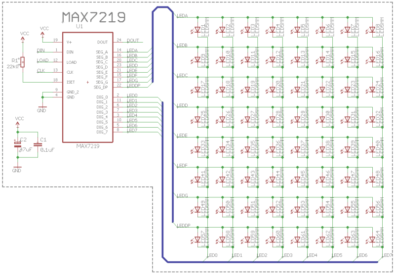
If you notice, the segment pins of the MAX7219 are connected to the LED matrix rows, and the digit pins are connected to the LED matrix columns. As such, the way the MAX7219 operates, it will allow us to cycle through digits (or columns) turning on/off any segment (or LEDs) in any digit.
MAX7219 Initialization Sequence
Reading into the MAX7219 datasheet, the following steps need to be taken to initialize the device for usage:
Write
0x01to address0x0Cto power up the MAX7219Write
0x00to address0x09to put the MAX7219 in "No Decode" mode (see notes)Write
0x07to address0x0Bremoving any scan limit (see notes)Write
0x07to address0x0Achoosing a medium light intensity for the LEDs
📝 Notes
The "No Decode" mode is the one necessary for driving an LED matrix. Other modes are ones used for driving seven segment displays.
The scan limit controls how many digits are activated (displayed) in the case of hooking up the MAX7219 to seven segment displays. In the case of the LED dot matrix, however, the scan limit affects how many rows can be activated. Obviously, in the case of the 8x8 dot matrix, all rows need to be shown. However, this is a feature when connecting a series of seven segment displays, in some cases, some digits need not be used.
LED Matrix Control Sequence
Like I had mentioned earlier all that the code will be doing is activate the LEDs diagonally one at a time then deactivate them again. These are the steps:
Initialize a variable
xto keep track of the column and row index and initialize it with a value of1.Activate LED
xin rowxDelay 500 ms
Increment column and row index
(x = x + 1)If the last row is reached (
x = 8) resetxback to 1 else go back to step 2Deactivate all the LEDs in the row
xDelay 500 ms
Increment column and row index
(x = x + 1)If the last row is reached (
x = 8) resetxback to 1 else go back to step 1
It becomes clear that it would be convenient to wrap this implementation in some sort of loop. Let's move on to the implementation to see what the code looks like.
👨💻 Code Implementation
📥 Crate Imports
In this implementation, the following crates are required:
The
embedded-halcrate to import spi configuration parameters.The
esp_idf_halcrate to import the needed device hardware abstractions.
use embedded_hal::spi::*;
use esp_idf_hal::delay::FreeRtos;
use esp_idf_hal::gpio;
use esp_idf_hal::peripherals::Peripherals;
use esp_idf_hal::prelude::*;
use esp_idf_hal::spi::config::Config;
use esp_idf_hal::spi::*;
🎛 Initialization/Configuration Code
SPI Peripheral Configuration:
1️⃣ Obtain a handle for the device peripherals: Similar to all past blog posts, in embedded Rust, as part of the singleton design pattern, we first have to take the device peripherals. This is done using the take() method. Here I create a device peripheral handler named peripherals as follows:
let peripherals = Peripherals::take().unwrap();
2️⃣ Obtain handles for SCLK, MOSI, and CS pins: Here I need to configure and obtain handles for the SCLK, MOSI, and CS pins so that they can be controlled by the SPI peripheral. As shown earlier, the SCLK, MOSI, and CS pins are connected to gpio0, gpio2, and gpio3, respectively. As such, I obtain handles for sclk, mosi and cs as follows:
let sclk = peripherals.pins.gpio0;
let mosi = peripherals.pins.gpio2;
let cs = peripherals.pins.gpio3;
3️⃣ Instantiate a SPI Driver: In the esp-idf-hal SPI is configured in two steps. The first step involves instantiating a SPIDriver followed by a SPIDeviceDriver . The SPIDriver defines the peripheral instance to be used, the pins, and configurations like dma. The SPIDeviceDriver on the other hand, configures SPI behavior like modes, baudrate, and bit order, among others. In this application, we're going to use SPI2 since SPI0 and SPI1 have restrictions according to the documentation.
To configure/instantiate we need to use use the new method in the SPIDriver abstraction struct to instantiate a SPI2 instance. If we examine the new method signature in SPIDriver, it looks like this:
pub fn new<SPI: SpiAnyPins>(
    _spi: impl Peripheral<P = SPI> + 'd,
    sclk: impl Peripheral<P = impl OutputPin> + 'd,
    sdo: impl Peripheral<P = impl OutputPin> + 'd,
    sdi: Option<impl Peripheral<P = impl InputPin + OutputPin> + 'd>,
    config: &DriverConfig
) -> Result<Self, EspError>
The method takes five parameters, a spi instance, pins instances, and a DriverConfig instance reference. As such, we can create a handle spi_drv for spi2 as follows:
let spi_drv = SpiDriver::new(
    peripherals.spi2,
    sclk,
    mosi,
    None::<gpio::AnyIOPin>,
    &SpiDriverConfig::new(),
)
.unwrap();
A couple of things to note, first is that since the communication is in one direction I don't need to pass a pin instance to sdi (serial input or MISO). As a result, I am passing a None::<gpio::AnyIOPin> since sdi requires an Option. The type annotation is necessary because the compiler would otherwise blow an error. Second, is that I by instantiating a SpiDriverConfig using it's new method, I am electing for the default configuration which is sufficient for our application.
3️⃣ Configure the SPI peripheral channel: This is the second step to configure SPI behavior using the SPIDeviceDriver. In our case, there are two items we need to configure, the baud rate and the mode according to the MAX7219 specification. SPIDeviceDriver has a new method that takes three parameters, an instance of a SPIDriver, an instance of a (cs) pin, and a spi::config::Config configuration as follows:
pub fn new(
    driver: T,
    cs: Option<impl Peripheral<P = impl OutputPin> + 'd>,
    config: &Config
) -> Result<Self, EspError>
Additionally, the Config struct contains several members allowing us to configure the SPI driver and is defined as follows:
pub struct Config {
    pub baudrate: Hertz,
    pub data_mode: Mode,
    pub write_only: bool,
    pub duplex: Duplex,
    pub bit_order: BitOrder,
    pub cs_active_high: bool,
    pub input_delay_ns: i32,
}
Looking into the source code, the Config struct defaults are sufficient except for the baudrate and the data_mode. For convenience, I create a separate handle config for the SPI configuration as follows:
let config = Config::new().baudrate(2.MHz().into()).data_mode(Mode {
    polarity: Polarity::IdleLow,
    phase: Phase::CaptureOnFirstTransition,
});
The baudrate and the mode are configured according to the MAX7219 requirements. Both Polarity and Phase are enums with different options. In my instance, I chose the Polarity::IdleLow option and Phase::CaptureOnFirstTransition option. The choices correspond to what is known as SPI Mode 0 which is what the MAX7219 datasheet defines as the mode of operation. Additionally, the MAX7219 datasheet states that the device can handle up to 10 MHz as a maximum rate so I only chose an arbitrary value of 2 MHz under the stated limit. Following that, I instantiate the SPIDeviceDriver and pass the SPIDriver handle spi_drv , the handle for the cs pin, and a reference to the SPIDeviceDriver configuration config:
let mut spi = SpiDeviceDriver::new(spi_drv, Some(cs), &config).unwrap();
This is it for configuration! Let's now jump into the application code.
📱 Application Code
In the software design described, the first step requires that we write '0x01' to address '0x0C' to power up the MAX7219. As explained earlier, the way data is written to the MAX7219 is by clocking in 16 bits MSB first while the CS line is low. After that, the CS line needs to be asserted to latch the data. To send data over SPI there is a write method that has the following signature:
pub fn write(&mut self, write: &[u8]) -> Result<(), EspError>
As can be observed, the write method takes a slice of bytes sending everything the slice contains byte after byte. Additionally, in the write method takes care of asserting and unasserting the cs pin. As such, to achieve the described earlier, the following code was written:
// Prepare Data
let data: u8 = 0x01;
let addr: u8 = 0x0C;
let send_array: [u8; 2] = [addr, data];

// Send Data
spi.write(&send_array).unwrap();
As can be seen, the 16-bit word is packaged in a single array that is passed into the write method so that it can be transmitted while the write method keeps CS low. data refers to data that is being written to the addr address in the MAX7219. After that CS is asserted by write to latch the transmitted array. This code is repeated exactly in the same manner with different addr and data contents for the remaining steps 2, 3, and 4 required to initialize the MAX7219.
All that is left now is to write the code for drawing the diagonal line on the LED matrix. Looking at the steps described earlier, essentially all that needs to be done, is to cycle through addresses/rows 1 to 8 then send 8-bit data that represents individual LEDs/columns to light up. Since we are drawing a diagonal line then one LED needs to be lit up in each row at a time. The LED that is lit will shift one bit to the left as we cycle through the rows. This can be wrapped in a for loop as follows:
let mut data: u8 = 1;
for addr in 1..9 {
      let send_array: [u8; 2] = [addr, data];
      data = data << 1;

      spi.write(&send_array).unwrap();

      FreeRtos::delay_ms(500_u32);
}
Note also the delay that is introduced at the end of the loop so that the LEDs can be noticed as they turn on and off. Next, we want to clear the rows one by one so a second similar loop can be introduced as follows:
for addr in 1..9 {
      let send_array: [u8; 2] = [addr, data];
      spi.write(&send_array).unwrap();
      FreeRtos::delay_ms(500_u32);
}
Keep in mind here that data already has a zero value from the previous loop, so it does not need to be updated.
This is it!
📱Full Application Code
Here is the full code for the implementation described in this post. You can additionally find the full project and others available on the apollolabs ESP32C3 git repo. Also, the Wokwi project can be accessed here.
use esp_idf_sys::{self as _}; // If using the `binstart` feature of `esp-idf-sys`, always keep this module imported

use embedded_hal::spi::*;
use esp_idf_hal::delay::FreeRtos;
use esp_idf_hal::gpio;
use esp_idf_hal::peripherals::Peripherals;
use esp_idf_hal::prelude::*;
use esp_idf_hal::spi::config::Config;
use esp_idf_hal::spi::*;

fn main() -> ! {
    // Setup handler for device peripherals
    let peripherals = Peripherals::take().unwrap();

    // Create handles for SPI pins
    let sclk = peripherals.pins.gpio0;
    let mosi = peripherals.pins.gpio2;
    let cs = peripherals.pins.gpio3;

    // Instantiate SPI Driver
    let spi_drv = SpiDriver::new(
        peripherals.spi2,
        sclk,
        mosi,
        None::<gpio::AnyIOPin>,
        &SpiDriverConfig::new(),
    )
    .unwrap();

    // Configure Parameters for SPI device
    let config = Config::new().baudrate(2.MHz().into()).data_mode(Mode {
        polarity: Polarity::IdleLow,
        phase: Phase::CaptureOnFirstTransition,
    });

    // Instantiate SPI Device Driver and Pass Configuration
    let mut spi = SpiDeviceDriver::new(spi_drv, Some(cs), &config).unwrap();

    // Application

    // 1) Initalize Matrix Display

    // 1.a) Power Up Device

    // - Prepare Data to be Sent
    // 8-bit Data/Command Corresponding to Matrix Power Up
    let data: u8 = 0x01;
    // 4-bit Address of Shutdown Mode Command
    let addr: u8 = 0x0C;
    // Package into array to pass to SPI write method
    // Write method will grab array and send all data in it
    let send_array: [u8; 2] = [addr, data];

    // - Send Data
    // Shift in 16 bits by passing send_array (bits will be shifted MSB first)
    // Note that write method handles the CS pin state
    spi.write(&send_array).unwrap();

    // 1.b) Set up Decode Mode

    // - Prepare Information to be Sent
    // 8-bit Data/Command Corresponding to No Decode Mode
    let data: u8 = 0x00;
    // 4-bit Address of Decode Mode Command
    let addr: u8 = 0x09;
    // Package into array to pass to SPI write method
    // Write method will grab array and send all data in it
    let send_array: [u8; 2] = [addr, data];

    // - Send Data
    // Shift in 16 bits by passing send_array (bits will be shifted MSB first)
    spi.write(&send_array).unwrap();

    // 1.c) Configure Scan Limit

    // - Prepare Information to be Sent
    // 8-bit Data/Command Corresponding to Scan Limit Displaying all digits
    let data: u8 = 0x07;
    // 4-bit Address of Scan Limit Command
    let addr: u8 = 0x0B;
    // Package into array to pass to SPI write method
    // Write method will grab array and send all data in it
    let send_array: [u8; 2] = [addr, data];

    // - Send Data
    // Shift in 16 bits by passing send_array (bits will be shifted MSB first)
    spi.write(&send_array).unwrap();

    // 1.c) Configure Intensity

    // - Prepare Information to be Sent
    // 8-bit Data/Command Corresponding to (15/32 Duty Cycle) Medium Intensity
    let data: u8 = 0x07;
    // 4-bit Address of Intensity Control Command
    let addr: u8 = 0x0A;
    // Package into array to pass to SPI write method
    // Write method will grab array and send all data in it
    let send_array: [u8; 2] = [addr, data];

    // - Send Data
    // Shift in 16 bits by passing send_array (bits will be shifted MSB first)
    spi.write(&send_array).unwrap();

    loop {
        let mut data: u8 = 1;
        // Iterate over all rows of LED matrix
        for addr in 1..9 {
            // addr refrences the row data will be sent to
            let send_array: [u8; 2] = [addr, data];
            // Shift a 1 with evey loop
            data = data << 1;

            // Send data just like earlier
            spi.write(&send_array).unwrap();

            // Delay for 500ms to show effect
            FreeRtos::delay_ms(500_u32);
        }

        // Clear the LED matrix row by row with 500ms delay in between
        for addr in 1..9 {
            let send_array: [u8; 2] = [addr, data];
            spi.write(&send_array).unwrap();
            FreeRtos::delay_ms(500_u32);
        }
    }
}
Conclusion
In this post, an LED dot matrix display simple application was created by configuring and controlling the MAX7219 LED driver. This was using the SPI peripheral for the ESP32C3 and the esp-idf-hal. Have any questions? Share your thoughts in the comments below 👇.
If you found this post useful, and to keep up to date with similar posts, here's the list of channels you can follow/subscribe to:


Top comments (0)